


Introduction
In the rapidly evolving landscape of enterprise technology, data remains the most critical asset for organizational success. However, the path from a high-level business idea to a fully functional, optimized database is rarely straightforward. Misalignment between business stakeholders and technical teams often leads to costly rework, scope creep, and systems that fail to meet actual user needs. To bridge this gap, organizations must adopt a disciplined, structured approach to data modeling.
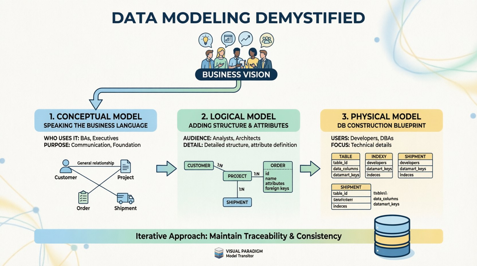
Data modeling is not merely a technical exercise; it is a communication framework that translates abstract business requirements into concrete technical specifications. By breaking this complex process into three distinct but interconnected stages—Conceptual, Logical, and Physical—teams can ensure traceability, maintain consistency, and ultimately deliver a database architecture that truly reflects the business vision. This case study explores how this iterative methodology transforms vague concepts into robust digital infrastructure, serving as a blueprint for successful data-driven initiatives.
Visualizing the Journey: The Three-Stage Model
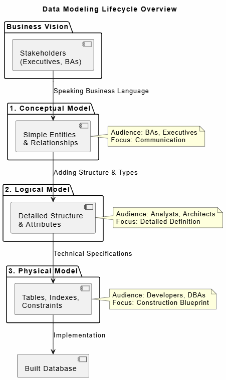
The following diagram illustrates the high-level workflow of the data modeling process, highlighting the transition from business vision through the three modeling stages to the final technical implementation.
@startuml
title Data Modeling Lifecycle Overview

skinparam backgroundColor #FEFEFE
skinparam defaultFontName Arial

package "Business Vision" {
    [Stakeholders\n(Executives, BAs)] as Biz
}

package "1. Conceptual Model" {
    [Simple Entities\n& Relationships] as Concept
}

package "2. Logical Model" {
    [Detailed Structure\n& Attributes] as Logic
}

package "3. Physical Model" {
    [Tables, Indexes,\nConstraints] as Phys
}

[Built Database] as DB

Biz --> Concept : Speaking Business Language
Concept --> Logic : Adding Structure & Types
Logic --> Phys : Technical Specifications
Phys --> DB : Implementation

note right of Concept
  Audience: BAs, Executives
  Focus: Communication
end note

note right of Logic
  Audience: Analysts, Architects
  Focus: Detailed Definition
end note

note right of Phys
  Audience: Developers, DBAs
  Focus: Construction Blueprint
end note

@enduml
Figure 1: High-Level Data Modeling Workflow – From Business Vision to Technical Implementation
Case Study: Transforming Retail Operations at “Nexus Retail Group”
Background and Challenge
Nexus Retail Group, a mid-sized omnichannel retailer with over 200 physical locations and a growing e-commerce platform, faced significant operational challenges. Their legacy inventory system was siloed, leading to stock discrepancies, delayed shipments, and an inability to provide real-time visibility to executives. The C-suite envisioned a unified “Single Source of Truth” platform that would integrate sales, inventory, logistics, and customer data.
However, early attempts to build this system failed because developers built databases based on assumed technical requirements rather than validated business processes. The resulting system was technically sound but operationally useless. Nexus Retail Group then engaged a data architecture team to restart the project using a structured, three-stage data modeling approach.
Phase 1: The Conceptual Model – Aligning Stakeholders
The first step involved stripping away all technical jargon. The data architecture team conducted workshops with Business Analysts (BAs), regional managers, and C-level executives. The goal was not to define database tables, but to agree on what the business needed to track and how entities related to one another in plain language.
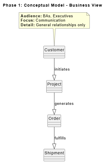
Using simple entity-relationship diagrams, the team mapped out core concepts such as “Customer,” “Order,” “Shipment,” and “Product.” Relationships were defined broadly—for example, “A Customer places an Order” and “An Order results in a Shipment.” At this stage, no data types or column names were discussed. The output was a visual map that every executive could understand and validate. This phase established the foundational vocabulary and ensured that the technical team was solving the right business problems before writing a single line of code.
@startuml
title Phase 1: Conceptual Model - Business View

hide circle
skinparam classAttributeIconSize 0
skinparam packageStyle rectangle

entity "Customer" as Cust
entity "Project" as Proj
entity "Order" as Ord
entity "Shipment" as Ship

Cust --|> Proj : initiates
Proj --|> Ord : generates
Ord --|> Ship : fulfills

note top of Cust
  **Audience:** BAs, Executives
  **Focus:** Communication
  **Detail:** General relationships only
end note

@enduml
Figure 2: Conceptual Model Example – High-Level Entity Relationships Without Technical Detail
Phase 2: The Logical Model – Defining Structure Without Technology
Once the conceptual model was signed off by business leadership, the project transitioned to the Logical Model. This phase was led by Data Analysts and Enterprise Architects who acted as translators between the business vision and technical implementation.
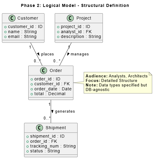
In this stage, the simple entities from Phase 1 were expanded into detailed structures. Attributes were defined (e.g., “Order” now included order_id, order_date, total_amount, and status). Relationships were refined to include cardinality (one-to-many, many-to-many). Crucially, while data types were specified (e.g., VARCHAR, DATE), they remained technology-agnostic. The team did not yet decide whether the database would be PostgreSQL, Oracle, or MongoDB. This abstraction allowed the logical model to serve as a stable contract between business needs and future technical decisions, ensuring that the structure was driven by data requirements rather than platform limitations.
@startuml
title Phase 2: Logical Model - Structural Definition

class Customer {
  + customer_id : ID
  + name : String
  + email : String
}

class Project {
  + project_id : ID
  + analyst_id : FK
  + description : String
}

class Order {
  + order_id : ID
  + customer_id : FK
  + order_date : Date
  + total : Decimal
}

class Shipment {
  + shipment_id : ID
  + order_id : FK
  + tracking_num : String
  + status : String
}

Customer "1" -- "0..*" Order : places >
Order "1" -- "0..*" Shipment : generates >
Project "1" -- "0..*" Order : manages >

note right of Order
  **Audience:** Analysts, Architects
  **Focus:** Detailed Structure
  **Note:** Data types specified but
  DB-agnostic
end note

@enduml
Figure 3: Logical Model Example – Detailed Attributes and Relationships Independent of Database Technology
Phase 3: The Physical Model – The Construction Blueprint
With a validated logical model in hand, the project moved to the Physical Model. This phase was owned by Developers and Database Administrators (DBAs). Here, the abstract structures were translated into exact database specifications tailored to the chosen technology stack.
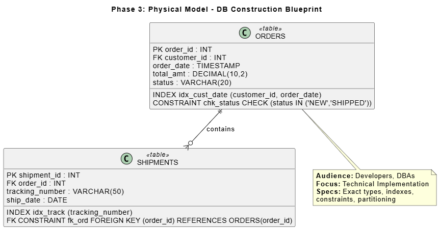
The team defined precise table schemas, including primary keys, foreign keys, indexes for performance optimization, and constraints to enforce data integrity. For example, the logical “Order” entity became a physical orders table with specific column definitions, partitioning strategies for historical data, and indexing on customer_id and order_date to support frequent query patterns. This blueprint served as the definitive guide for database construction, eliminating ambiguity during the build phase and ensuring that the final system would perform efficiently under production loads.
@startuml
title Phase 3: Physical Model - DB Construction Blueprint

class ORDERS <<table>> {
  PK order_id : INT
  FK customer_id : INT
  order_date : TIMESTAMP
  total_amt : DECIMAL(10,2)
  status : VARCHAR(20)
  __
  INDEX idx_cust_date (customer_id, order_date)
  CONSTRAINT chk_status CHECK (status IN ('NEW','SHIPPED'))
}

class SHIPMENTS <<table>> {
  PK shipment_id : INT
  FK order_id : INT
  tracking_number : VARCHAR(50)
  ship_date : DATE
  __
  INDEX idx_track (tracking_number)
  FK CONSTRAINT fk_ord FOREIGN KEY (order_id) REFERENCES ORDERS(order_id)
}

ORDERS ||--o{ SHIPMENTS : contains

note bottom of ORDERS
  **Audience:** Developers, DBAs
  **Focus:** Technical Implementation
  **Specs:** Exact types, indexes,
  constraints, partitioning
end note

@enduml
Figure 4: Physical Model Example – Exact Table Definitions, Indexes, and Constraints for Database Deployment
Ensuring Success Through Iteration and Traceability
Throughout all three phases, Nexus Retail Group adhered to two critical principles: iteration and traceability. The process was not linear; feedback from the Physical Model phase occasionally revealed gaps in the Logical Model, which in turn required revisiting the Conceptual Model. This iterative loop ensured that no requirement was lost in translation.
To maintain consistency across layers, the team utilized a Model Transitor tool. This integration platform automatically synchronized changes between the conceptual, logical, and physical models, providing real-time traceability. When a business stakeholder requested a change to how “Shipments” were tracked, the impact could be instantly visualized across all three modeling layers, preventing downstream inconsistencies and reducing rework by an estimated 40%.
Outcomes
By adopting this structured data modeling approach, Nexus Retail Group successfully deployed their unified data platform six months ahead of the revised schedule. The new system reduced inventory discrepancies by 85%, improved order fulfillment times by 30%, and provided executives with real-time dashboards that accurately reflected business operations. More importantly, the organization established a repeatable data modeling framework that has since been applied to subsequent digital transformation initiatives, significantly reducing time-to-value for new data projects.
Conclusion
The journey from business vision to database implementation is fraught with potential missteps, but a structured data modeling methodology provides a reliable compass. As demonstrated in the Nexus Retail Group case study, separating concerns into Conceptual, Logical, and Physical models allows organizations to align stakeholders, define robust structures, and execute precise technical builds without losing sight of the original business objectives.
Success in data modeling hinges not just on technical expertise, but on disciplined communication, iterative refinement, and unwavering traceability. By treating data modeling as a collaborative, multi-stage process rather than a one-time technical task, organizations can transform ambiguous business ideas into resilient, high-performing data architectures. In an era where data is the cornerstone of competitive advantage, mastering this structured approach is not optional—it is essential for sustainable digital growth.
References
- Design Database with Professional ERD Software: Create and communicate visual database design with an ERD tool that provides graphical representation of database tables, their columns, and inter-relationships. Supports conceptual, logical, and physical ER models along with AI-powered diagram generation.
- The Ultimate AI ERD Tool & Database Design Software: A robust database design tool that bridges the gap between SQL Design concepts and technical implementation, ensuring data integrity through normalization while supporting Cloud Modeling and rapid iteration. Offers both Desktop and Online versions for different workflow needs.
- Complete Guide to Database Design with Visual Paradigm ERD Tools: Comprehensive guide covering Visual Paradigm’s ERD suite, combining professional-grade manual modeling with AI-driven automation. Details conceptual, logical, and physical ER models, AI-powered features like automatic foreign key generation, and support for multiple database systems.
- Visual Paradigm Database Management Guides: Collection of guides covering reverse engineering ERD from database and DDL, generating database from ERD, patching design changes to database, and copying SQL statements from entities in ERD.
- Reverse Engineering ERD from DDL: Learn how to reverse engineer Entity Relationship Diagrams from .ddl and .sql files. Visual Paradigm forms nice ERDs out of create and alter statements written in DDL, allowing you to produce data dictionaries or revise designs.
- Free ERD Tool – Visual Paradigm Online: Free online ERD tool for creating entity relationship diagrams without installation. Provides cloud-based diagramming capabilities for database design.
- ERD Diagram Tool: Professional ERD diagram tool for designing databases with graphical representation of tables, columns, and relationships. Supports various database design phases and modeling standards.
- ERD Diagram Tool (Traditional Chinese): Traditional Chinese version of the ERD diagram tool page, providing database design capabilities with entity relationship diagram support.
- Database Engineering Tools: Comprehensive database engineering tools including forward and reverse engineering capabilities, ORM code generation, and support for multiple database management systems.
- ERD Tool for Database Design: Specialized ERD tool focused on database design, providing visual modeling capabilities for creating and managing database schemas with entity relationship diagrams.
- Modeling Data with ERD: User guide section on modeling data using Entity Relationship Diagrams, covering techniques for creating and managing database models within Visual Paradigm.
- Reverse DDL Tutorial: Step-by-step tutorial on how to reverse engineer ERD from DDL files, demonstrating the process of converting SQL definition language into visual database diagrams.
- ERD & ORM Guide: Documentation covering Entity Relationship Diagrams and Object-Relational Mapping integration, explaining how to map object models to data models and vice versa.
- ERD Tool (Traditional Chinese): Traditional Chinese version of the ERD tool solution page, offering database design and entity relationship diagram capabilities for Taiwanese and Chinese-speaking users.
