
Mastering UML Sequence Diagrams in Visual Paradigm: A Step-by-Step Guide
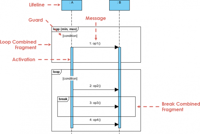
In the realm of software architecture and system design, clarity is paramount. Visual Paradigm stands as a premier tool for visualizing complex interactions within a system. This tutorial focuses on the Sequence Diagram, a dynamic model that illustrates how objects interact with one another over time. We will deconstruct the specific elements shown in our reference diagram—specifically lifelines, messages, and combined fragments—to help you build robust, professional-grade models.
Foundational Elements: Lifelines and Activation
Before diving into complex logic, we must establish the actors in our system. In Visual Paradigm, these are represented by Lifelines.
- Lifelines: As shown in the diagram, the blue rectangles at the top (labeled
:Aand:B) represent the participating objects or instances. The vertical dashed line extending downwards is the lifeline, representing the existence of the object over time. - Activation Bars: The solid blue vertical bars along the lifeline are known as activation bars (or focus of control). They indicate the period during which an object is performing an action or waiting for a response. In our diagram, the bar on
:Bbecomes active when it receives theop1()message from:A.
Interaction Logic: Messages and Guards
Once the actors are established, we define their behavior through messages. These are the arrows connecting the lifelines.
- Synchronous Messages: The arrow labeled
1: op1()represents a synchronous call. Object:Asends a request to:Band waits for the response before continuing its own execution. - Guards: You will notice a small box labeled
[condition]near the message arrow. This is a Guard. It acts as a conditional statement; the message is only sent if the condition inside the brackets evaluates to true. This allows you to model branching logic directly within the diagram.
Advanced Control Flow: Combined Fragments
The true power of Visual Paradigm lies in its ability to handle control structures through Combined Fragments. These are the large rectangular frames surrounding groups of interactions.
1. The Loop Fragment
The diagram features a frame labeled loop. This combined fragment is used to model iterative behavior.
- Operator: The keyword
loopindicates that the enclosed interaction occurs repeatedly. - Constraints: You can specify the range of iterations using the syntax
loop (min, max). For example,loop (1, 5)would mean the action inside happens between 1 and 5 times. If the condition[condition]remains true, the loop continues.
2. The Break Fragment
Within the larger loop structure, we see a nested frame labeled break. This is a specialized combined fragment used to model early termination of a loop.
- Functionality: If the interaction inside the
breakframe is triggered (e.g.,3: op3()), the outerloopis immediately exited, and control flows to the end of the sequence. - Nesting: Visual Paradigm allows for deep nesting of fragments. In this diagram, the
breakis nested inside theloop, which itself is nested inside the main sequence flow.
@startuml
actor User
participant "System" as Sys

User -> Sys : 1: op1()
activate Sys

loop [Condition met]
  Sys -> Sys : 2: op2()

  alt [Break Condition]
    Sys -> Sys : 3: op3()
    break
  else [Normal Condition]
    Sys -> Sys : 4: op4()
  end

end
deactivate Sys
@endumlConclusion
By mastering these elements—Lifelines, Messages, and Combined Fragments—you can create highly detailed sequence diagrams that serve as blueprints for your developers. Visual Paradigm’s visual interface makes managing these complex interactions intuitive, allowing you to focus on the logic of your system rather than the drawing mechanics.