
Mastering Asynchronous Message Flow in UML Sequence Diagrams
In the realm of software architecture and system design, understanding how components communicate is fundamental. Among the various UML (Unified Modeling Language) diagrams used to visualize system interactions, the Sequence Diagram is perhaps the most critical for defining the timing and order of messages exchanged between objects. While synchronous calls are intuitive, many modern systems rely heavily on asynchronous communication to ensure efficiency and scalability.
This tutorial explores the concept of Asynchronous Messages, specifically focusing on how they are modeled in UML sequence diagrams using the standard notation of a solid line with an open arrowhead. We will break down the underlying mechanics, the architectural implications, and how to represent this using industry-standard modeling tools.
The Mechanics of Asynchronous Communication
In a synchronous message exchange, the sender initiates a request and then enters a blocked state, waiting for the receiver to process the request and send a return signal. This can lead to bottlenecks, especially in high-throughput systems.
Asynchronous communication changes this dynamic entirely. In this model, the sender transmits a message and continues its own execution immediately, without waiting for a response. This is the backbone of event-driven architectures and multi-threaded applications where decoupling is essential.
Visual Representation: The Open Arrowhead
When modeling this in a UML Sequence Diagram, clarity is paramount. To distinguish an asynchronous message from a synchronous one, UML specifies a distinct visual syntax:
- Sender: The object initiating the action.
- Receiver: The object accepting the message.
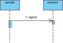
- The Arrow: Unlike the solid line with a filled triangular arrowhead used for synchronous calls, an asynchronous message is represented by a solid line with an open arrowhead.
Consider the diagram provided in our context. We see a “sender” object and a “receiver” object. The message is labeled “1: signal”. The arrow connecting them is solid but terminates in an open, hollow triangle. This visual cue tells the developer that once the signal is sent, the sender’s control flow is not suspended.
Why Use Asynchronous Messages?
The choice to model an interaction as asynchronous is rarely accidental. It is usually a deliberate architectural decision driven by performance and system responsiveness requirements.
1. Event-Driven Systems
In event-driven architectures, components react to events rather than direct function calls. For example, a user logging in triggers a “UserLoggedIn” signal. The system processes this signal to update a database, send a welcome email, and log the activity. The user interface does not freeze while the email is sent; it receives the signal and moves on.
2. Multi-threaded Applications
When multiple threads are running concurrently, blocking one thread to wait for another is inefficient. Asynchronous messaging allows a thread to offload a task to another thread (the receiver) and continue processing other work.
Implementing the Model with Visual Paradigm
To create professional-grade sequence diagrams that adhere to these standards, developers and architects often rely on specialized CASE (Computer-Aided Software Engineering) tools. Visual Paradigm is a leading tool in this space, offering robust support for UML modeling.
Using Visual Paradigm, you can easily construct the diagram shown in our example. The tool enforces the standard UML notation rules, ensuring that when you switch a message type to “Asynchronous,” the arrow automatically renders with the correct open arrowhead. This eliminates manual formatting errors and ensures that the diagram remains a valid technical specification.
For those working within the Visual Paradigm environment, the workflow is intuitive:
- Create a new Sequence Diagram.
- Add your “sender” and “receiver” lifelines.
- Select the message tool.
- Configure the message properties to set the direction as “Asynchronous”.
- Label the message (e.g., “signal”) and assign a sequence number (e.g., “1”).
This structured approach ensures that your architectural documentation is not just a sketch, but a precise blueprint of the system’s logic.
Code Logic: Representing the Flow
When translating these visual diagrams into executable code or pseudo-code, the asynchronous nature is often reflected in the way methods are invoked. Here is a conceptual representation of how the “sender” handles the “signal” message:
// Asynchronous Message Flow Representation

class Sender {
    void processRequest() {
        // 1. Send the signal to the receiver
        // In asynchronous flow, this call returns immediately
        receiver.sendSignal("data_payload");

        // 2. Sender continues execution immediately
        // It does NOT wait for the receiver to finish processing
        System.out.println("Signal sent. Continuing with other tasks...");
        doOtherWork();
    }
}

class Receiver {
    void sendSignal(String data) {
        // Processing happens in a separate thread or queue
        // This might be a long-running task
        processBackgroundTask(data);
    }
}
Conclusion
Understanding the distinction between synchronous and asynchronous messaging is vital for designing robust software systems. By mastering the visual representation of these interactions—specifically the open arrowhead for asynchronous signals—you can create sequence diagrams that accurately reflect the behavior of complex, high-performance applications. Whether you are modeling a simple event handler or a distributed microservices architecture, clear modeling with tools like Visual Paradigm ensures that your design intent is preserved from the diagram to the code.