
Mastering Hospital Bed Allocation: A UML Sequence Diagram Tutorial
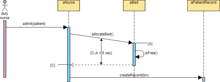
In the complex ecosystem of hospital management systems, the process of admitting a patient is a critical workflow that requires precise coordination between various actors and system components. This tutorial delves into the system architecture behind a Hospital Bed Allocation process, utilizing a Sequence Diagram to visualize the temporal flow of messages.
We will analyze this architecture using Visual Paradigm, a leading UML modeling tool. By breaking down the diagram, we will understand how the system manages the interaction between a Duty Nurse, a Bed, and a Patient Record to ensure efficient resource allocation.
Understanding the Sequence Diagram Architecture
A Sequence Diagram is a type of interaction diagram because it shows how objects interact with each other in time. In the context of our Hospital Bed Allocation system, the diagram maps out the specific sequence of method calls required to successfully admit a patient.
Let’s break down the key participants (objects) and their roles:
- duty nurse: Represented by the stick figure (actor) on the far left. This is the human user initiating the workflow by requesting patient admission.
- aNurse: The system object representing the nurse’s interface or service layer. It acts as the controller for the admission process.
- aBed: A system object representing the specific bed resource. It contains logic to determine availability.
- aPatientRecord: A system object responsible for persisting the new patient’s data.
Step-by-Step Workflow Analysis
The diagram illustrates a synchronous flow of control. Here is how the interaction unfolds chronologically from top to bottom:
1. The Admission Request
The process begins when the duty nurse sends the message admit(patient) to the aNurse object. This is a synchronous message (solid line with a filled arrowhead), indicating that the nurse waits for the system to acknowledge the request.
2. Bed Allocation Logic
Upon receiving the request, aNurse activates its execution bar and delegates a task to the aBed object by invoking allocateBed(). This step is crucial for ensuring that a physical resource is secured before the patient is formally processed.
3. Availability Check ({A})
Inside the aBed object, a self-message is triggered: isFree(). This represents a loop or an internal query where the bed checks its own state. The label {A} marks this specific point in the sequence. If the bed is free, the allocation proceeds; otherwise, an error might be returned.
4. Time Constraint Validation ({C-A})
One of the most important architectural constraints shown is the time guard: {C-A < 5 sec}. This annotation indicates a performance requirement or a timeout mechanism. It implies that the duration between the start of the allocation (A) and the completion or response (C) must be strictly less than 5 seconds. If this constraint is violated, the system may trigger a fallback mechanism or alert the nurse.
5. Record Creation
Once the bed is successfully allocated, the aNurse object sends a final message to the aPatientRecord object: createRecord(bn). This creates the necessary database entry for the patient, linking them to the assigned bed.
Modeling Best Practices with Visual Paradigm
When recreating this diagram in Visual Paradigm, pay attention to the activation bars (the blue vertical rectangles). These bars represent the period during which an object is actively performing an action. In this model:
- The aNurse activation bar spans the entire duration of the interaction, highlighting its role as the central coordinator.
- The aBed activation bar is short, reflecting the quick nature of the allocation check.
Conclusion
This Sequence Diagram provides a clear blueprint for developers and stakeholders to understand the Hospital Bed Allocation system. By visualizing the interactions between the Nurse, Bed, and Patient Record, we can identify potential bottlenecks, such as the 5-second time constraint, and optimize the system for better performance.