


In the landscape of software architecture and systems engineering, clarity is paramount. Yet, a persistent misconception lingers within the community regarding the Unified Modeling Language (UML). Many practitioners view Profile Diagrams as merely a lighter, less detailed version of a Class Diagram. They assume that if a Class Diagram describes structure, a Profile Diagram must describe a simplified version of that structure. This view is fundamentally incorrect and can lead to significant errors in model-driven design and interoperability.
Understanding the distinction is not just an academic exercise; it is a critical requirement for building robust, extensible systems. When you confuse the two, you risk applying the wrong constraints, misinterpreting model metadata, and failing to achieve the modularity that modern engineering standards demand. This guide dissects the technical realities of UML Profiles, separating myth from fact with precision.
Understanding the UML Metamodel 🧩
To grasp why a Profile Diagram differs from a Class Diagram, one must first look beneath the surface of the diagramming syntax. UML is not merely a drawing tool; it is a specification language built upon a metamodel. The metamodel defines the rules for creating models. Think of the metamodel as the grammar of a language, and the model as the sentence.
- Class Diagrams operate within the core definitions of the UML metamodel. They define instances of the
Classifiermetaclass. - Profile Diagrams operate on the metamodel itself. They define extensions to the metamodel.
This distinction is structural. A Class Diagram describes a system using existing building blocks. A Profile Diagram creates new building blocks that can then be used by Class Diagrams. You cannot simply draw a Profile Diagram to replace a Class Diagram because they serve different layers of the abstraction hierarchy.
The Core Distinction: Extension vs. Definition 🔍
The primary function of a Profile Diagram is to customize the UML specification for a specific domain. It allows architects to introduce domain-specific terminology without altering the core UML standard. This is achieved through the concept of stereotypes.
Consider the workflow of a standard Class Diagram. You define a class named Invoice. You define its attributes and relationships. This is standard UML. Now, consider a financial domain where you need to specify that an Invoice is legally binding, has a tax ID, and must be audited annually. If you add these as attributes, you are mixing domain logic with structural data.
A Profile Diagram solves this by creating a stereotype called <<FinancialDocument>>. This stereotype extends the Class metaclass. It adds properties (tagged values) like taxID and auditRequired. When you apply this stereotype to your Invoice class in a Class Diagram, you inherit these constraints.
Therefore:
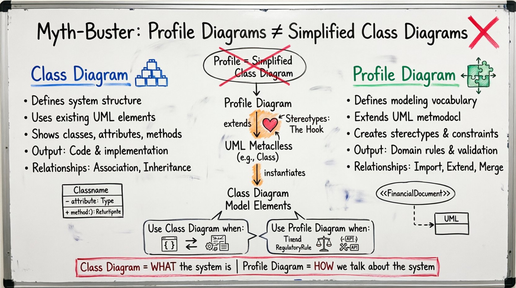
- Class Diagram: Defines the implementation structure of the system.
- Profile Diagram: Defines the vocabulary and constraints used to describe that structure.
Viewing a Profile as a simplified Class Diagram ignores the extension mechanism. A Profile is a package that imports existing UML definitions and extends them. It does not replace them. It adds to them.
Structural Anatomy Comparison 📊
To visualize the difference, we must look at the elements that populate each diagram. While both diagrams use boxes and lines, the semantics attached to those elements differ significantly.
| Feature | Class Diagram | Profile Diagram |
|---|---|---|
| Primary Element | Class | Profile Package |
| Relationship Type | Association, Aggregation, Inheritance | Import, Extend, Merge |
| Metaclass Target | Instances of UML elements | UML Metaclasses (e.g., Class, Association) |
| Purpose | Describe System State | Describe Modeling Rules |
| Output | Code, Implementation Specs | Domain Vocabulary, Validation Rules |
The table above highlights that while they may look similar visually, their internal logic is divergent. A Class Diagram describes what the system is. A Profile Diagram describes how we talk about the system.
Stereotypes: The Heart of Profile Diagrams ❤️
The stereotype is the defining feature of a Profile Diagram. It acts as a hook that connects your custom profile to the standard UML metamodel. Without stereotypes, a Profile Diagram is just a package with no function.
When you define a stereotype, you are essentially creating a new sub-class of an existing UML metaclass. For example, if you create a stereotype for a database table, you are extending the Class metaclass. You are saying, “Treat this class exactly like a Class, but also obey these specific rules.”
- Application: Stereotypes are applied to model elements. You drag the stereotype from the Profile onto a Class in a Class Diagram.
- Display: In a diagram, stereotypes appear in guillemets (e.g.,
<<Type>>) above the element name. - Constraints: Stereotypes can carry constraints. These are often written in OCL (Object Constraint Language) to enforce logic.
If you treat a Profile Diagram as a simplified Class Diagram, you might try to draw relationships between stereotypes as if they were relationships between classes. This is invalid. Stereotypes define properties for classes; they do not typically inherit from one another in the structural sense used in Class Diagrams.
Constraints and Tagged Values 🔒
Class Diagrams use attributes and operations to define data. Profile Diagrams use Tagged Values and Constraints. This is a crucial distinction for data modeling.
A Tagged Value in a Profile is a key-value pair that applies to the element it is attached to. Unlike a standard attribute in a Class Diagram, which becomes a field in a database or a member in a class, a Tagged Value is metadata. It describes the class, it is not part of the class’s runtime state.
- Attribute: Part of the object’s identity.
public int age; - Tagged Value: Part of the model’s definition.
<<Database>> table = "Users"
Furthermore, Profile Diagrams often contain constraints. These are logical rules that must be satisfied for the model to be valid. A Class Diagram might show that a Customer has an Order. A Profile Diagram might define that an Order cannot exist without a Customer. This is a constraint on the relationship, defined in the Profile, applied to the Class Diagram.
Confusing these leads to runtime errors. If you define a Tagged Value as a Class Attribute, your code generator might create a field that does not exist in the domain, or vice versa. You must maintain the boundary between structural data and modeling metadata.
When to Use a Profile Diagram 📅
Identifying the correct time to utilize a Profile Diagram is essential for maintaining a clean architecture. You should introduce a Profile when you find yourself repeating the same set of properties or constraints across multiple classes.
- Domain Specificity: If your system operates in a specific domain (e.g., healthcare, finance, aerospace), standard UML terms may be insufficient. A Profile allows you to define terms like
<<PatientRecord>>or<<FlightControl>>. - Tool Integration: If you are integrating with external tools that expect specific metadata, a Profile ensures that metadata is standardized across the project.
- Regulatory Compliance: If you need to enforce specific rules (e.g., data encryption tags), a Profile defines these rules centrally rather than scattering them across every class.
Using a Profile in these scenarios ensures that if the rules change, you update the Profile, and the change propagates to all elements using that stereotype. This is the essence of model-driven engineering. A Class Diagram does not offer this level of centralized governance for structural definitions.
When to Use a Class Diagram 🏗️
Conversely, the Class Diagram remains the workhorse for describing the actual system logic. You use a Class Diagram when you need to visualize the implementation details.
- Implementation Details: Define the methods, attributes, and visibility (private, public) that developers will code against.
- Relationships: Show how objects interact, navigate, and aggregate data. This includes associations, dependencies, and generalizations.
- State Changes: Show how data flows through the system. This includes the lifecycle of an object.
Do not use a Profile Diagram to show how a Customer object calls a Order method. That is a structural relationship that belongs in a Class Diagram or a Sequence Diagram. The Profile defines that the Customer might be a <<VerifiedUser>>, but the Class Diagram defines the relationship between them.
The Relationship Between Profiles and Packages 📦
It is important to understand that a Profile is technically a Package. However, it is a specialized package with specific rules. A standard Package groups elements for organization. A Profile Package extends the metamodel.
When you create a Profile, you are creating a namespace. You can import this Profile into other diagrams. This is different from importing a standard Package. Importing a Profile imports the definitions of the stereotypes and constraints. Importing a Package imports the classes and objects.
This distinction affects how models are merged. If you merge two Class Diagrams, you are combining system parts. If you merge two Profiles, you are combining vocabularies. You must ensure that the stereotypes do not conflict. For example, you cannot have two different definitions for <<Service>> in the same model context without resolving the conflict.
Interoperability and Standardization 🌐
One of the strongest arguments for using Profile Diagrams is interoperability. In large-scale systems, different teams might use different tools. A Profile Diagram acts as a contract between these tools.
- Standard Exchange: If Team A uses Tool X and Team B uses Tool Y, they can agree on a Profile. Both tools understand the stereotypes defined in the Profile.
- Validation: Automated tools can validate a Class Diagram against a Profile. If a class lacks the required stereotype, the validation fails before deployment.
- Documentation: The Profile Diagram serves as the documentation for the modeling rules. It tells the reader, “This is how we model our system,” whereas the Class Diagram tells the reader, “This is what our system looks like.”
Relying solely on Class Diagrams for this purpose creates ambiguity. One team might interpret a relationship as “one-to-one” while another interprets it as “one-to-many.” A Profile can define the constraint explicitly, removing the ambiguity.
Common Missteps in Model Design 🚫
Despite the clear definitions, practitioners often make errors when integrating Profiles and Class Diagrams. Recognizing these pitfalls helps maintain model integrity.
- Over-Engineering: Creating a Profile for every small detail. Profiles should be reserved for significant domain concepts. If you create a stereotype for every attribute, your model becomes cluttered and hard to maintain.
- Ignoring Constraints: Defining a stereotype but forgetting to add the OCL constraints that give it meaning. A stereotype without constraints is just a label.
- Mixing Layers: Putting implementation logic (like method signatures) into a Profile. Profiles are for metadata, not implementation.
- Version Drift: Updating a Profile without updating the Class Diagrams that rely on it. This leads to broken models where elements reference stereotypes that no longer exist.
Strict discipline is required. The Profile must be the source of truth for the metadata, and the Class Diagram must be the source of truth for the structure.
Best Practices for Profile Management ✅
To ensure your modeling efforts are effective, adhere to these management practices.
- Centralize Profiles: Keep your Profile Diagrams in a central repository. Do not distribute them across multiple folders unless there is a clear domain separation.
- Version Control: Treat Profile definitions as code. Use version control to track changes to stereotypes and constraints.
- Documentation: Every stereotype in a Profile should have a clear description. Explain what it means and when to use it.
- Testing: Validate your Class Diagrams against the Profile regularly. Ensure that the applied stereotypes are correct and the constraints are satisfied.
- Simplicity: Keep the metamodel extensions simple. Avoid deep inheritance hierarchies within stereotypes unless absolutely necessary.
Final Thoughts on Model Architecture 🧠
The distinction between Profile Diagrams and Class Diagrams is a matter of architectural discipline. A Class Diagram maps the terrain. A Profile Diagram maps the rules of the road. You need both to navigate successfully.
When you understand that a Profile Diagram is a mechanism for metamodel extension rather than a simplified structural view, you unlock a higher level of precision in your designs. You move from describing what the system looks like to defining how the system should be defined. This shift is critical for any organization serious about Model-Driven Architecture and long-term system maintainability.
Do not conflate the two. Use the Class Diagram to build the structure. Use the Profile Diagram to define the language. Together, they form a complete picture of your system’s design intent.

