


In software architecture, clarity and modularity are essential for building scalable, maintainable systems. One of the most effective tools for visualizing the structural design of a system is the UML Component Diagram. This diagram type provides a high-level view of how a system is broken into distinct, self-contained components and how they interact through well-defined interfaces. It’s particularly valuable during the design phase, helping teams align on system structure before implementation begins.
Visual Paradigm stands out as a powerful platform for creating and managing UML diagrams, including component diagrams. With support for all 14 UML 2.x types, it enables architects and developers to model complex systems with precision. But what makes it truly powerful today is its integration with AI-driven modeling tools—transforming diagramming from a manual task into an intelligent, conversational process.
What Is a UML Component Diagram?
A UML Component Diagram illustrates the physical structure of a system by showing how software components are organized and how they depend on one another. Components can represent modules, libraries, services, or even external systems. They are connected through interfaces, which define how components communicate.
Key elements include:
- Components: Represented as rectangles with a
<<component>>stereotype. - Provided Interfaces: Shown as a “lollipop” shape, indicating services a component offers.
- Required Interfaces: Represented as a “socket,” showing what services a component needs from others.
These diagrams are part of the implementation view in UML, focusing on the actual building blocks of a system rather than its behavior.
Why Use Visual Paradigm for Component Diagrams?
Visual Paradigm is a full-featured modeling environment that supports the entire lifecycle of system design—from conceptual modeling to code generation. It provides the tools needed to create accurate, professional-grade UML diagrams.
Standardized Notation and Precision
The platform ensures correct UML notation, including the proper use of lollipops and sockets. This helps avoid confusion during team reviews and ensures diagrams are understood consistently across stakeholders.
Traceability and Integration
Components in Visual Paradigm can be linked to real-world artifacts—like user stories in Jira or source code files. This traceability ensures that architectural decisions remain aligned with requirements and development progress.
Model-Driven Engineering
Visual Paradigm supports forward engineering (generating code from a diagram) and reverse engineering (creating a diagram from existing code). This bidirectional capability enables teams to work efficiently between design and implementation.
How AI Enhances Component Diagram Design
The integration of AI into Visual Paradigm has significantly improved the modeling experience. The AI Chatbot and Text-to-Diagram engine allow users to generate component diagrams using natural language, reducing the time and effort required to create them.
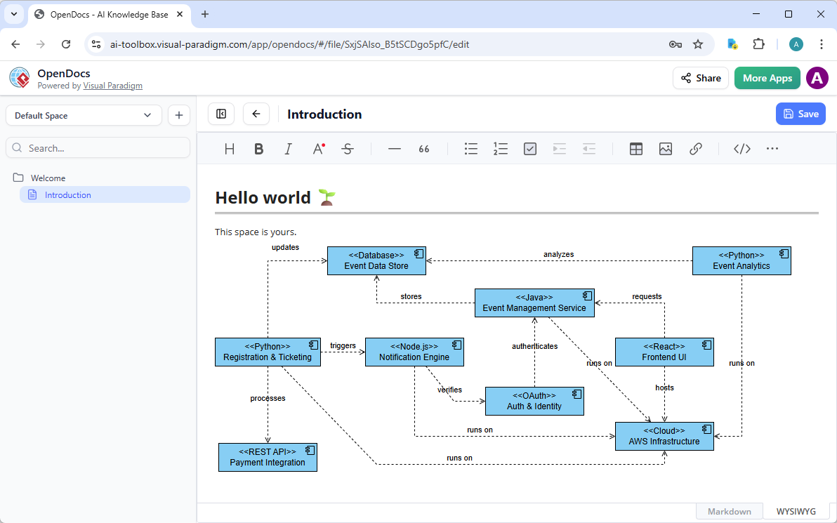
OpenDocs: AI Powered Knowledge Management
Documentation often kills momentum. You finish a great component diagram, export it as an image, paste it into a doc… and it goes stale the moment you tweak the model.
OpenDocs fixes that. This knowledge management platform lets you embed dynamic, editable diagrams right into your documents, wikis, or reports—perfect for strategy guides, architecture overviews, or team handbooks that include component views.
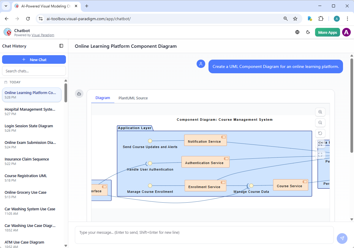
AI Chatbot
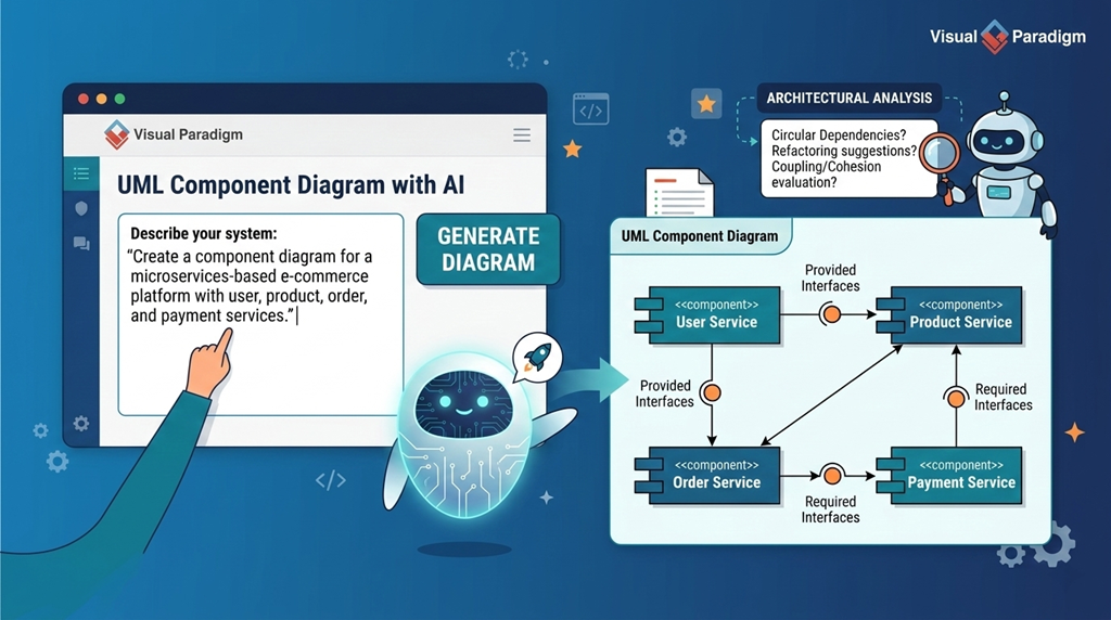
Stuck staring at a blank canvas? Visual Paradigm’s AI Visual Modeling Chatbot eliminates that. Just describe what you need in plain language—”Create a component diagram for an e-commerce system with payment gateway, inventory service, and user authentication modules, showing provided and required interfaces.”
The chatbot generates your diagram instantly. You review it, then iterate: “Add a dependency from inventory to database,” “Explain the ports,” or “Generate a report summarizing these components.” It handles refinements, explanations, and even exports.
Example Use Case: E-Commerce Platform
Imagine designing a scalable e-commerce system. A component diagram would include:
- User Service: Manages authentication and profiles.
- Product Service: Handles product catalog and inventory.
- Order Service: Processes orders and manages fulfillment.
- Payment Service: Handles transactions and payment gateways.
Each service exposes and consumes interfaces. For instance, the Order Service requires the Product Service to check stock and the Payment Service to process payments. Visual Paradigm’s AI can generate this structure with minimal input, allowing you to focus on refinement and analysis.
Best Practices for Using UML Component Diagrams
- Focus on Interfaces: Define clear contracts between components. Avoid tight coupling.
- Keep Components Coherent: Each component should have a single responsibility.
- Use Names That Reflect Functionality: Names like
UserManagementComponentare more informative thanComponent1. - Document Dependencies: Use notes or comments to explain complex interactions.
Conclusion
UML Component Diagrams remain a vital tool for software architects. When combined with a modern, AI-powered platform like Visual Paradigm, they become even more powerful—enabling faster, smarter, and more accurate modeling.
Whether you’re designing a new system or refactoring an existing one, Visual Paradigm’s AI-enhanced tools help you create diagrams that are not only visually clear but also technically sound and aligned with real-world development practices.
- What is a Component Diagram? – Visual Paradigm UML Guide: Comprehensive introduction to UML component diagrams, which illustrate the modular structure of a software system through reusable components, interfaces, provided/required ports, connectors, and dependencies; covers notation (components, interfaces, assembly/deployment connectors), examples (e.g., online shopping system), and best practices for high-level architecture design and component reuse.
- UML Component Diagram: Definitive Guide to Modular Design with AI – Visual Paradigm AI Chatbot: In-depth guide explaining component diagrams for encapsulating functionality and interfaces, with AI-powered generation from text descriptions (e.g., “e-commerce checkout module with payment gateway integration”), iterative refinements via chat, automatic detection of provided/required interfaces, and export to Visual Paradigm for further modeling and code generation.
- Beginner’s Guide to UML Component Diagrams – Visual Paradigm Blog: Accessible tutorial for newcomers covering purpose (showing high-level software structure and dependencies), key elements (components, interfaces, ports, connectors), notation basics, simple examples (e.g., library system with database and UI components), and tips for starting with Visual Paradigm’s drag-and-drop editor.
- Visual Paradigm AI Chatbot for UML Diagramming: Interactive AI assistant that generates and refines UML diagrams—including component diagrams—from natural language prompts, supports adding/removing components/interfaces, adjusting relationships, querying explanations, suggesting modular improvements, and seamless import to desktop/cloud for collaborative architecture work.
- Practical Guide to UML Modeling – Visual Paradigm: Hands-on UML resource emphasizing model-driven engineering: creating consistent models (including component diagrams), automatic code generation from components/interfaces, reverse engineering from code to diagrams, synchronization, and integration with other UML views for end-to-end software development.
- Comprehensive Review: Visual Paradigm’s AI Diagram Generation Features – Fliplify: Third-party evaluation of AI tools for rapid, standards-compliant UML creation (including component diagrams), conversational editing, high accuracy with clear prompts, usability across skill levels, and strong productivity gains in modular software architecture design.
- Introduction to UML Diagrams in Visual Paradigm – ArchiMetric: Overview of Visual Paradigm’s UML support, highlighting practical workflows for component diagrams (modular decomposition, interface specification), alongside other types, with AI assistance for faster modeling, validation, and integration into larger architectural blueprints.
- Visual Paradigm AI Diagram Generator: Comprehensive Guide – Cybermedian: Detailed walkthrough of AI text-to-diagram capabilities, including component diagrams: describe system modules/interfaces in natural language, generate editable structures with ports/connectors, apply real-time refinements, ensure UML compliance, and leverage for architectural analysis and modular design.
- Comprehensive Guide to Visual Paradigm’s AI-Powered UML & Modeling Ecosystem (2025–2026) – Cybermedian: Forward-looking analysis of AI integration across UML (component, class, sequence, etc.), featuring text-to-model automation, intelligent critique, iterative chatbot support, code generation from components, and ecosystem enhancements for scalable, modular software architecture in future development cycles.
- Visual Paradigm AI vs. Standard Text-to-Diagram Tools: Guide to Living Models – Cybermedian: Comparison highlighting Visual Paradigm’s advantages—standards-trained AI, contextual/iterative refinements, living models (synchronized diagrams/code), superior quality for component-based design, and reduced manual effort compared to generic generators.
- Major Upgrade: AI UML Component Diagram Generation – Visual Paradigm Updates: Release notes on enhanced AI for component diagrams: improved interface/port detection, better assembly/deployment connector logic, cleaner layouts, support for complex modular systems, and higher fidelity to UML 2.5 standards via the chatbot.
- Visual Paradigm AI Diagram Generator Expansion – ArchiMetric: Article on AI’s growing scope beyond UML (including component diagrams) to DFDs, ERDs, mind maps, and more; emphasizes instant generation, cross-diagram consistency, and support for diverse modeling needs in software and business contexts.
