Business process management relies heavily on the ability to communicate complex workflows clearly. When stakeholders describe how a process should work, they often use natural language, acronyms, and internal jargon. These descriptions are prone to misinterpretation. Translating these textual requirements into a standardized visual format eliminates ambiguity. Business Process Model and Notation (BPMN) serves as the universal language for this task. By converting abstract requirements into concrete diagrams, organizations create a single source of truth.
This guide details the methodology for mapping business rules to BPMN elements without relying on specific tools. The focus remains on the logical structure, semantic accuracy, and the discipline required to maintain high-quality process models. Following this approach ensures that the resulting diagrams are not just pictures, but functional blueprints for automation, analysis, and improvement.
📋 Understanding the Source Material: Business Requirements
The foundation of any accurate process model lies in the quality of the input. Business requirements are often scattered across emails, meeting notes, legacy documents, and verbal conversations. Before drawing a single shape, an analyst must synthesize these inputs into a coherent set of rules. This phase requires active listening and rigorous questioning.
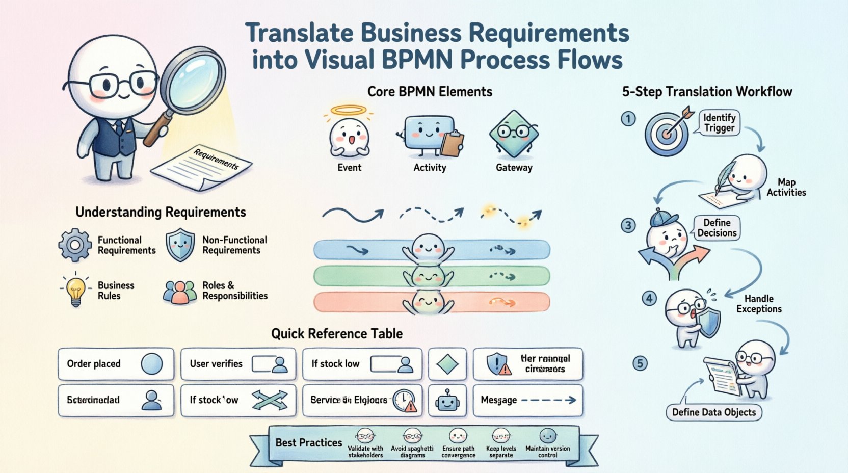
- Functional Requirements: These define what the system or process must do. For example, “The system must validate the credit card before shipping.”
- Non-Functional Requirements: These define constraints such as time, security, or compliance. For example, “Data must be encrypted during transmission.”
- Business Rules: Specific conditions that dictate decision points. For example, “If the order value exceeds $1,000, manager approval is required.”
- Roles and Responsibilities: Who performs the work? This determines the swimlanes or pools in the diagram.
During the elicitation phase, avoid accepting vague statements like “handle the error.” Ask for the specific trigger, the specific action, and the specific outcome. Ambiguity in the requirements leads to ambiguity in the model. A well-defined requirement set allows for a direct mapping to BPMN symbols.
🛠️ The Blueprint: Core BPMN Concepts for Translators
To translate requirements effectively, one must understand the grammar of the notation. BPMN 2.0 provides a standardized set of elements. Mastery of these elements ensures the diagram is readable by any stakeholder, regardless of their technical background.
1. Flow Objects
These are the building blocks of the process path.
- Events: Represented by circles. They indicate something that happens during the process. Start events trigger the flow, intermediate events occur during the process, and end events terminate the flow.
- Activities: Represented by rounded rectangles. These are the tasks or work performed. They can be manual tasks, service tasks, or user tasks.
- Gateways: Represented by diamonds. These control the divergence and convergence of the path. They determine how the process branches based on conditions.
2. Connecting Objects
These link the flow objects together to show the sequence.
- Sequence Flow: Solid arrows showing the order of activities.
- Message Flow: Dashed arrows showing communication between pools or lanes.
- Association: Dotted lines linking data objects to activities.
3. Swimlanes and Pools
Organizing the diagram by responsibility is critical for clarity.
- Pools: Represent a distinct participant, such as an organization or a system.
- Lanes: Subdivide a pool to represent specific roles, departments, or systems within that participant.
⚙️ The Translation Workflow: From Text to Diagram
Transforming text into a visual model requires a systematic approach. Rushing this step often results in complex, unreadable diagrams. The following workflow ensures logical consistency.
Step 1: Identify the Trigger
Every process begins with an event. Look for keywords like “receive,” “submit,” “start,” or “trigger.” In BPMN, this maps to a Start Event. If the trigger is external, such as an email, use a Message Start Event. If it is time-based, use a Time Start Event.
Step 2: Map the Activities
Scan the text for verbs. “Review,” “Approve,” “Calculate,” and “Send” are all actions. Map these to Tasks. Group related tasks within the appropriate Lane based on the actor mentioned in the requirements.
Step 3: Define Decision Points
Look for conditional logic. Phrases like “If,” “When,” “Else,” “Or,” and “Unless” signal the need for a Gateway.
- Exclusive Gateway: Used when only one path is taken (e.g., Yes/No).
- Inclusive Gateway: Used when one or more paths might be taken.
- Parallel Gateway: Used when all paths must be taken simultaneously.
Step 4: Handle Exceptions
Business requirements often omit what happens when things go wrong. Ask specific questions about failures. If a credit card declines, what happens? Map these to Error Events or Escalation Events. This ensures the model represents the real-world behavior, not just the ideal scenario.
Step 5: Define Data Objects
Processes manipulate information. Identify nouns in the text that represent data, such as “Invoice,” “Order Form,” or “Customer Record.” Represent these as Data Objects and associate them with the tasks that create, read, update, or delete them.
🔄 Handling Complexity: Gateways, Events, and Exceptions
Complexity often arises from the interaction of multiple conditions and parallel paths. Misusing gateways is a common error. To maintain efficiency in translation, adhere to the following rules.
Rule 1: Match the Gateway to the Logic If the requirement states “Choose one option,” use an Exclusive Gateway. If it states “Perform all tasks,” use a Parallel Gateway. Using a Parallel Gateway for a binary choice will break the logic and confuse the reader.
Rule 2: Ensure Path Convergence Every gateway that splits the flow must eventually converge the flow back to a single path, or terminate the process. Never leave a path hanging. If a branch leads to an end, ensure the other branch also leads to an end or a merge point.
Rule 3: Manage Event Sub-Processes For complex exception handling, consider using an Event Sub-Process. This allows you to define a specific event (like a timeout) that triggers a sub-process within the main flow. This keeps the main diagram clean and modular.
📊 Mapping Requirement Types to BPMN Elements
The following table provides a quick reference for translating common requirement phrases into BPMN notation.
| Requirement Phrase | BPMN Element | Context |
|---|---|---|
| “When an order is placed…” | Start Event | Initiates the process flow. |
| “The user must verify the email…” | User Task | Human interaction required. |
| “If the stock is low…” | Exclusive Gateway | Binary decision point. |
| “Send notification AND update log” | Parallel Gateway | Simultaneous actions. |
| “If the server crashes…” | Boundary Error Event | Exception handling on a task. |
| “After 24 hours…” | Intermediate Timer Event | Time-based delay. |
| “The system calculates tax” | Service Task | Automated system action. |
| “Send invoice to customer” | Message Flow | Communication outside the lane. |
🧐 Validation: Ensuring Accuracy with Stakeholders
A diagram is only as good as its validation. Once the translation is complete, the model must be reviewed against the original requirements. This step is not about asking for approval; it is about verifying logic.
- Walkthroughs: Conduct a session where you walk through the diagram step-by-step. Ask stakeholders to confirm if the flow matches their mental model.
- Scenario Testing: Use the diagram to test edge cases. “What happens if the user cancels after step 3?” Trace the path on the diagram to see if the model handles it.
- Gap Analysis: Compare the requirements document line-by-line with the diagram. If a requirement exists in the text but not the diagram, it is a gap. If the diagram has a step not in the text, it may be an assumption that needs verification.
Validation often reveals that requirements were incomplete. For example, stakeholders might realize they forgot to mention a compliance check. This is a valuable outcome of the modeling process. It forces the organization to think through the process before implementation begins.
🛡️ Common Pitfalls in Process Modeling
Even experienced analysts make mistakes. Recognizing these pitfalls early prevents technical debt in the process design.
1. The “Big Ball of Mud”
Trying to model every possible scenario in a single diagram leads to spaghetti. The diagram becomes unreadable. Instead, use sub-processes to hide complexity. Break large processes into manageable chunks.
2. Ignoring the End State
A process must end. Ensure every path leads to an End Event. If a path loops infinitely, it indicates a logic error or a missing termination condition.
3. Overusing Gateways
Using gateways for simple flow control is unnecessary. Sometimes a simple sequence flow is sufficient. Gateways should be reserved for actual decision logic.
4. Mixing Levels of Detail
Do not mix high-level strategic flows with low-level implementation details. Keep the top-level diagram focused on the major phases. Drill down into sub-processes for the granular steps.
📈 Maintaining the Model Over Time
A process model is a living document. Business requirements change, regulations evolve, and systems update. A model that is not maintained becomes obsolete quickly.
- Version Control: Maintain a history of changes. Note who updated the model and why.
- Review Cadence: Schedule periodic reviews. Quarterly or bi-annual reviews ensure the model stays aligned with current operations.
- Change Management: When requirements change, update the model immediately. Do not wait for the next big project to fix the diagram.
Documentation should accompany the model. A legend or a requirements traceability matrix helps new team members understand the context. This ensures continuity when personnel changes occur.
🔍 Advanced Considerations for Data and Integration
Modern processes rarely exist in a vacuum. They interact with data systems and external partners. Translating these interactions requires attention to detail.
Data Objects and Information Flow
Processes transform data. Ensure every task that consumes or produces data has a corresponding Data Object. Use associations to link the data to the task. This clarifies what information is needed to perform the work and what is produced.
External Collaboration
When a process involves an external party, use a separate Pool. Use Message Flows to show the exchange of information. Do not draw sequence flows across pools unless you are using a specific collaboration pattern. This maintains the boundary of responsibility.
Service Integration
When a task involves an API call or a backend service, label it as a Service Task. This distinguishes it from a manual User Task. This distinction is vital for automation engines later on.
🧩 Finalizing the Visual Presentation
While functionality is paramount, readability matters. A confusing layout hinders understanding. Follow these visual design principles.
- Direction: Flow should generally move from top to bottom or left to right. Avoid crossing lines.
- Alignment: Align tasks and gateways neatly. Use grids or guides if available.
- Labels: Keep text concise. If a label is too long, use a separate description or expand the shape.
- Color Usage: Use color sparingly. Reserve color for highlighting exceptions or specific states. Avoid rainbow diagrams.
By adhering to these principles, the diagram becomes a tool for communication rather than a source of confusion. The goal is clarity above all else.
🏁 Summary of Best Practices
Translating business requirements into BPMN flows is a skill that blends analytical thinking with visual design. It requires patience, precision, and a deep understanding of the domain. By following a structured workflow, validating with stakeholders, and avoiding common pitfalls, organizations can build robust process models.
These models serve as the backbone for operational efficiency. They reduce errors, clarify responsibilities, and provide a foundation for automation. The effort invested in accurate translation pays dividends in reduced rework and faster implementation. Focus on the logic, respect the notation, and prioritize the needs of the people who will use the diagram.
Continuous improvement is the key. As the business evolves, so must the model. Treat the diagram as a dynamic asset. Regular updates ensure it remains a true reflection of reality. With discipline and attention to detail, the translation from text to visual flow becomes a reliable bridge between business intent and technical execution.
