Business Process Model and Notation (BPMN) serves as the universal language for process modeling. It allows organizations to visualize workflows, define logic, and communicate complex operations across technical and non-technical teams. However, the precision of a diagram relies entirely on the correct use of its symbols. Misinterpreting a gateway or an event can lead to flawed automation, compliance risks, or operational bottlenecks.
This guide provides a detailed breakdown of BPMN 2.0 elements. We explore the specific functions of events, activities, gateways, and connecting objects. The goal is to ensure your diagrams are not just visually appealing, but logically sound and strictly compliant with the standard.
Understanding the Core Building Blocks 🧱
A BPMN diagram is constructed from four primary categories of elements. Each category serves a distinct purpose in defining the lifecycle of a business process. To create a robust model, one must understand the nuance between similar-looking shapes.
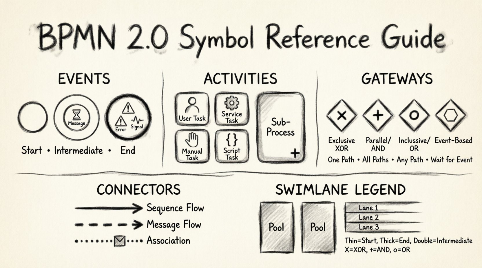
- Events: Things that happen. These are represented by circles and define the start, intermediate, or end of a flow.
- Activities: Work to be done. These are rounded rectangles representing tasks or sub-processes.
- Gateways: Decisions and synchronization. These diamonds control the path the flow takes.
- Connecting Objects: The arrows that link everything together.
1. Events: The Pulse of Your Process ⏱️
Events are the triggers and results of your process. They are depicted as circles. The thickness of the circle border indicates the type of event. Understanding the difference between these is critical for accurate simulation and execution.
Start Events 🟢
A start event marks the beginning of a process instance. It has no incoming sequence flow. The border of a start event is thin. Inside the circle, a symbol defines what triggers the process.
- Message Start: Triggered by receiving a message (e.g., an email or API call). Represented by an envelope icon.
- Timer Start: Triggered by a time condition (e.g., every Monday at 9 AM). Represented by a clock icon.
- Signal Start: Triggered by a signal broadcast to the system.
- Error Start: Rarely used, this represents a start triggered by a specific error condition.
End Events 🔴
End events signify the conclusion of a process instance. They have no outgoing sequence flow. The border is thick to indicate termination. Symbols inside define the outcome.
- Message End: Sends a message upon completion.
- Signal End: Broadcasts a signal to other processes.
- Error End: Indicates the process ended due to an error.
- Cancel End: Specifically for transactional processes or sub-processes, indicating a cancellation.
- Terminate End: Stops all running instances of the process immediately, regardless of other parallel paths.
Intermediate Events ⚪
Intermediate events occur between the start and end. They have both incoming and outgoing sequence flows. The border is thin, but there is a double-line circle inside to distinguish it from start and end events.
- Catching Events: The process waits for something to happen. Examples include catching a message, a timer, or a signal. The flow pauses until the condition is met.
- Throwing Events: The process generates something. Examples include sending a message or triggering a signal. This usually happens after a task completes.
- Compensation: Special handling for errors in long-running processes.
2. Activities: Defining the Work 🛠️
Activities represent the actual work performed within the process. They are drawn as rounded rectangles. The icon inside the rectangle indicates the specific type of activity.
Tasks 📝
A task is the smallest unit of work. It cannot be decomposed further within the context of the diagram.
- User Task: Work performed by a human actor. Requires human interaction.
- Service Task: Work performed by an IT system or service. No human intervention is needed.
- Manual Task: Work that will be done manually in the real world, perhaps outside the system.
- Script Task: Work performed by a script or code snippet.
- Business Rule Task: Work executed by a rule engine or policy.
- Send/Receive Task: Specific types of tasks for asynchronous messaging.
Sub-Processes 📂
When a process becomes too complex, it is broken down into sub-processes. This is represented by a rounded rectangle with a plus sign (+) at the bottom.
- Collapsed Sub-Process: Shows the plus sign. Details are hidden to keep the main diagram clean.
- Expanded Sub-Process: Shows the internal tasks and flows. Used for detailed documentation.
- Call Activity: A reference to a reusable process template defined elsewhere.
3. Gateways: The Logic Controllers 🔄
Gateways determine the flow path of the process. They are the most critical elements for logic control. Without proper gateway usage, a process cannot make decisions or handle parallel work streams.
Exclusive Gateway (XOR) ⚡
The exclusive gateway represents a decision point where only one path is taken. It looks like a diamond with an X inside. It is used when conditions are mutually exclusive.
- Logic: If Condition A is true, go Path A. If Condition B is true, go Path B. Only one path is active.
- Usage: Approval processes (Approved vs. Rejected), branching based on data values.
- Default Flow: If no condition matches, the default flow is taken. This must be clearly labeled.
Parallel Gateway (AND) ⚙️
The parallel gateway splits or merges flows simultaneously. It looks like a diamond with a + inside.
- Split: Creates multiple parallel paths. All paths execute simultaneously.
- Join: Waits for all incoming parallel paths to complete before proceeding.
- Usage: Sending a notification email and updating a database simultaneously. Waiting for multiple approvals before proceeding.
Inclusive Gateway (OR) 🌐
The inclusive gateway allows for one or more paths to be taken. It looks like a diamond with an o inside.
- Split: Evaluates conditions. If Condition A is true, Path A activates. If Condition B is true, Path B activates. Both can be true.
- Join: Waits for all active paths to complete. It does not wait for paths that were not taken.
- Usage: Complex branching where multiple options can be selected (e.g., selecting multiple shipping methods).
Event-Based Gateway ⚠️
This gateway waits for a specific event to occur. It looks like a diamond with a hexagon inside. It is used for waiting on external triggers.
- Logic: The process waits for one of several events to happen. Once one event occurs, the other potential paths are cancelled.
- Usage: Waiting for a payment confirmation or a timeout expiration.
Comparison of Gateway Types
| Gateway Type | Symbol | Split Logic | Join Logic |
|---|---|---|---|
| Exclusive (XOR) | X inside Diamond | Select exactly one path based on conditions. | Join single incoming path. |
| Parallel (AND) | + inside Diamond | Create all paths simultaneously. | Wait for all incoming paths to complete. |
| Inclusive (OR) | o inside Diamond | Activate any paths that match conditions. | Wait for all active paths to complete. |
| Event-Based | Hexagon inside | Wait for any event to occur. | Wait for the event that occurred. |
4. Connecting Objects: Linking the Flow 🔗
Connectors define how information and control pass between elements. The style of the arrow indicates the nature of the connection.
Sequence Flow 🟦
Sequence flow connects elements within the same process. It is a solid line with an open arrowhead.
- Function: Indicates the order of execution.
- Direction: Flows from top to bottom, left to right.
- Usage: Connecting tasks, events, and gateways within a single lane.
Message Flow 🟧
Message flow connects elements across different pools or participants. It is a dashed line with an open arrowhead.
- Function: Indicates the exchange of information between participants.
- Direction: Can cross lanes and pools.
- Usage: Sending a request from the Customer to the Supplier.
Association 🟩
Association links data artifacts or annotations to flow elements. It is a dashed line with a filled arrowhead (or open, depending on direction).
- Function: Provides context or data references without affecting flow control.
- Usage: Linking a document to a task, or a text note to a specific gateway.
5. Pools and Lanes: Organizing Responsibilities 🏊
Complex processes involve multiple parties. BPMN uses Pools and Lanes to visualize these relationships.
Pools 🟦
A pool represents a participant in the process. It is a container that holds the process definition. Each pool has its own independent start and end events.
- Public Pool: Represents an external organization or entity.
- Private Pool: Represents an internal department or system.
- Message Flow: Can only occur between different pools.
Lanes 🟨
Lanes are subdivisions within a pool. They represent specific roles, departments, or systems responsible for the activities in that section.
- Responsibility: Clarifies who performs which task.
- Visual Clarity: Helps trace hand-offs between roles.
- Swimlanes: Often used interchangeably with lanes to describe the horizontal or vertical division.
6. Common Patterns and Anti-Patterns 🛑
Even experienced modelers make mistakes. Recognizing common patterns and anti-patterns ensures the longevity and usability of your diagrams.
The Infinite Loop ⚠️
A sequence flow that returns to a previous point without a termination condition creates an infinite loop. In a diagram, this is acceptable if it represents a retry mechanism, but in execution, it causes system hangs.
- Solution: Ensure there is a count limit or a break condition in the loop.
Orphan Tasks
Tasks that have no incoming or outgoing connections are orphan tasks. They indicate an incomplete diagram.
- Solution: Connect all tasks to a logical flow path.
Missing Gateways
Parallel flows that are not properly joined or split can cause deadlocks. If a process splits into two parallel paths but only one joins back, the other path might hang indefinitely.
- Solution: Always use a Parallel Gateway to join all parallel branches.
7. Best Practices for Diagramming 📏
To maintain high-quality process documentation, adhere to these structural guidelines.
Consistency in Naming
- Use clear, action-oriented names for tasks (e.g., Review Invoice rather than Invoice).
- Name events based on the trigger (e.g., Invoice Received rather than Start).
- Label gateways with the condition (e.g., Amount > 1000).
Visual Hierarchy
- Place the Start Event at the top or left.
- Place the End Event at the bottom or right.
- Keep the flow direction consistent (Top-to-Bottom or Left-to-Right).
- Avoid crossing lines. Use bend points to smooth the flow.
Data Objects
- Represent data as document icons attached to tasks.
- Use associations to show what data is read or written.
- Do not place data objects on sequence flows; they belong to tasks or gateways.
8. Advanced Gateway Logic 🧠
Advanced modeling often requires nested gateways or complex conditions. It is vital to understand the interaction between different gateway types.
Nested Gateways
Placing a gateway inside another gateway can simplify complex logic. However, it increases the cognitive load for readers.
- Recommendation: Keep logic simple. If a gateway requires five conditions, consider breaking the process into sub-processes.
Event-Based Choice
When using an Event-Based Gateway, ensure that all waiting events are distinct. If two events can happen simultaneously, the behavior becomes undefined.
- Recommendation: Use explicit logic to prioritize one event over another if ambiguity exists.
9. Troubleshooting Common Symbol Confusions 🤔
Even experts sometimes confuse similar symbols. Here is a quick reference for the most common mix-ups.
Task vs. Service Task
- Task: Human work.
- Service Task: System work.
- Check: Does a person need to click a button? If yes, it is a Task. If the system does it automatically, it is a Service Task.
Parallel vs. Inclusive Gateway
- Parallel: All paths run.
- Inclusive: Selected paths run.
- Check: Is it possible for only one path to run? If yes, use Inclusive. If all must run, use Parallel.
Intermediate Catching vs. Throwing
- Catching: The process waits.
- Throwing: The process sends.
- Check: Is the arrow pointing into the event (Catching) or out of it (Throwing)?
10. Implementation Considerations 🚀
While this guide focuses on the notation, the implementation of these diagrams often involves execution engines. Understanding the notation ensures that the logic can be translated into code or workflow rules.
- Condition Evaluation: Ensure gateway conditions are testable expressions.
- Timeouts: Use Timer Intermediate Events for SLA tracking.
- Notifications: Use Message End Events to trigger external alerts.
Summary of Notation Rules 📜
Adhering to the BPMN standard ensures that your diagrams are portable and understandable by any stakeholder.
- Events are Circles: Start (Thin), End (Thick), Intermediate (Double Thin).
- Activities are Rounded Rectangles: Task (Icon inside), Sub-process (Plus inside).
- Gateways are Diamonds: XOR (X), AND (+), OR (o), Event (Hexagon).
- Connections are Lines: Sequence (Solid), Message (Dashed), Association (Dashed).
- Artifacts are Documents: Data, Group, Annotation.
By mastering these symbols, you create a foundation for process optimization. Clear diagrams reduce ambiguity, streamline communication, and facilitate accurate automation. The effort invested in learning the notation pays off in the clarity of the resulting business processes.
Remember, a diagram is a contract. If the logic is unclear, the execution will be flawed. Review your models regularly to ensure they still reflect the current business reality.

